Scrambling and Descrambling
I was recently asked for some support regarding the usage of Scramblers and Descramblers. So far to be honest, I didn’t had much time to dig-into the scramblers and descramblers problematic, but I do know, that there are interfaces such as the Xilinx’s Aurora 8/10 or Xilinx’s Aurora 64/66b, which uses these to enhance the protocol. Basically a scrambler/descrambler is a LSFR (Linear Shift Feedback Register) with a predefined length, custom feedback connection and a few XORs. As previously mentioned in one of my previous posts (HERE), these LSFRs are used in many fields and not only for link-communications, a very good example are the Golden Codes and the GPS satellite identification using its PRNS (Pseudo Random Sequence) – generated by a LSFR.
The feedback is described by a generating polynomial and examples are given below. The order of the polynomial relates to the LSFR’s length (Amount of D-FFs) . The implementation of any LSFR is quite straightforward in any Hardware Description Language (HDL). What is more interesting are the properties of the Scramblers: They just basically randomize the data. Why is that helpful? Well basically a randomized signals tends to have a better interference properties as it decreases the amount of spectral spurs to a minimum, so that they doesn’t interfere with other channels (PCIe or Display port lanes).
- Xilinx’s Aurora 8/10b Encoding: G(x) = 1 + X3 + X4 + X5 + X 16 (PG046)
- Xilinx’s Aurora 64/66b Encoding: G(x) = 1 + X39 + X58 (SP011)
- PCI-E V3.0 Encoding: G(x) = 1 + X2 + X5 + X8 + X16 +X21 + X23
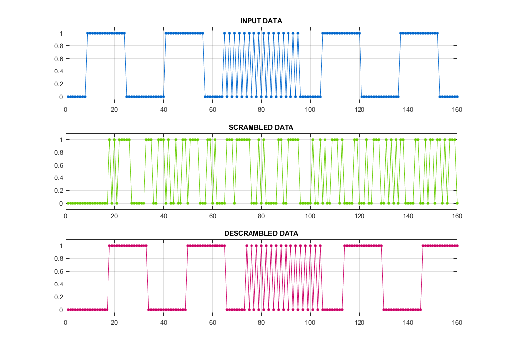
In my opinion, it is always a good decision to visualize thigs, so we start with a message signal, then we are going to scramble (randomize) it and after that, we are going to descramble it in order to verify that the scrambler and descrambler are working. I have in fact took an example from (HERE) and implemented in Matlab (Although its always a bit tricky to do things such as RTL outside the real hardware.) The polynomial is defined for SMPTE 259M G1(x) = 1 + X4 + X9, G2(x) = 1 + X1. These are actually chained and must therefore be descrambled (unchained) in the reverse order.

As you can see,the scrambled data looks random, which is the expected result. Furthermore, the decrambled signal gives us back the original message delayed by a few bits, which is also an expected behavior. The power spectrum of those signals would differ in such a way, that power of the scrambled signal would be spread among its peak, while the data (Depending on the data type! – Random data itself doesnt require scrambling) would have just a few peaks. That being said, sending “random” data is the best way to avoid interference. Of course a link / interface has to have a scrambler/descrambler on both the RX and TX, which should be however obvious. For testing and more variations about possible Polynomials see WIKI. I have actually implemented the LSFR inside Matlab in a way, that at first, I compute the following states for each shift registers (the T_ prefix variables) and after all is computed, I “clock” the calculated values into the registers in order to simulate RTL LSFR functionality.
Implementation of the Scrambler/Descrambler for Xilinx’s Aurora 8/10 is straightforward as well given a properly stated generating polynomial and using the Fibonacci LSFR. The descrambler is a so called “Self-Synchronization” descrambler, as it doesn’t possess any feedback. As a result, any error on the input causes the output to be invalid for a limited time. After the error is shifted-out, the descrambler is fully functional again. Furthermore, unlike the SMPTE 259M with NRZI, Aurora 8/10 requires only 1 polynomial – as stated before. “+” stands for XOR. The Scheme for Aurora 8/10 is shown below.

The code for the aurora simulation in Matlab is available ➡️ HERE ⬅️.
