HDMI 1080p Video with KCU116
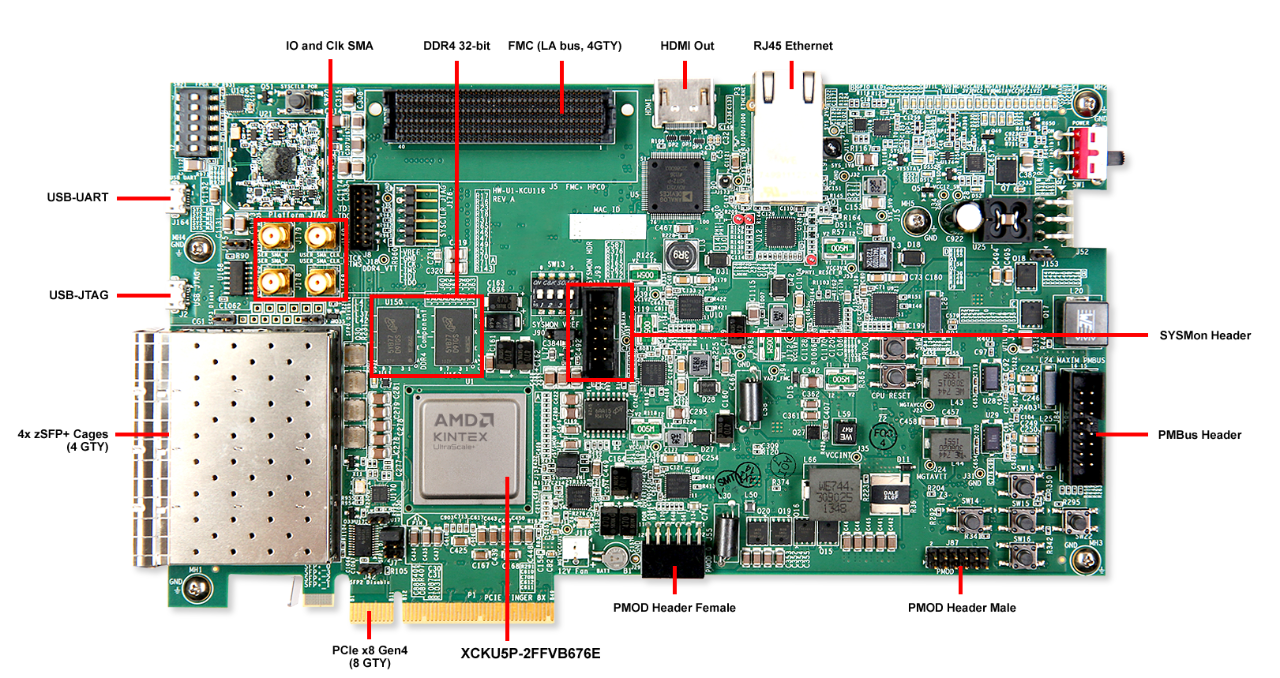
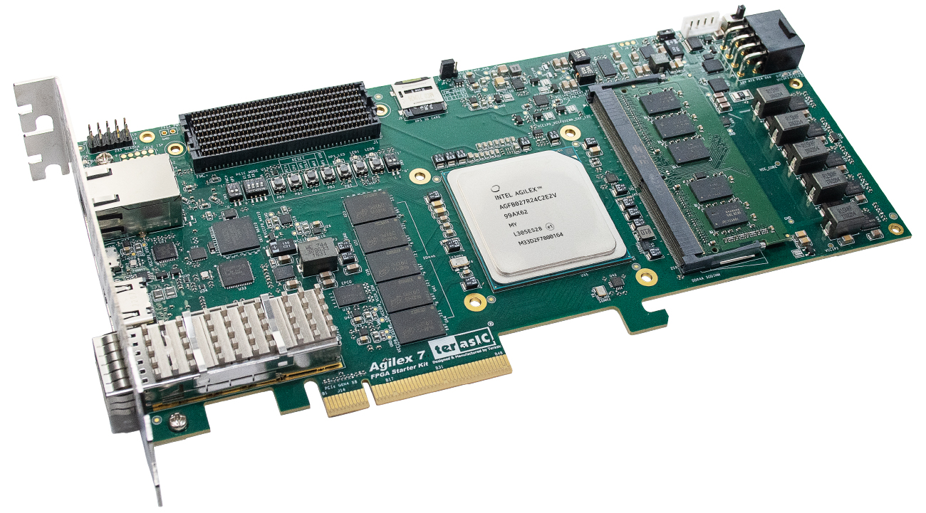
In order to showcase some of my self-developed IPs dedicated for video processing, I had to choose a proper development platform, that would allow me to quickly prototype and present results (IE reduce time to market). Because the only widely used video interface for FPGA is HDMI (Display Port requires the VESA membership for 5000$, Thanks VESA!), the choice was pretty much obvious. However some development boards require the developer to implement an entire HDMI interface, while some other utilize and external chip for this purpose. When I received the news about Intel Agilex 5/7 boards ( My favorite one being probably Agilex 7 Starter Kit from Terasic), I was really excited, as those would be probably the perfect development boards. What I realized however is that eventually one needs to utilize what is currently available on the market. And because I have so far overall positive experiences with the Xilinx's (AMD) boards (ZCU102, ZCU111 and VCU118) and their documentation, I have finally chosen the KCU116 platform (Even though It was tempting for me to use instead the Enclustra's XU9 SOM with the Mercury+ PE3 baseboard).
ADV7511 Configuration
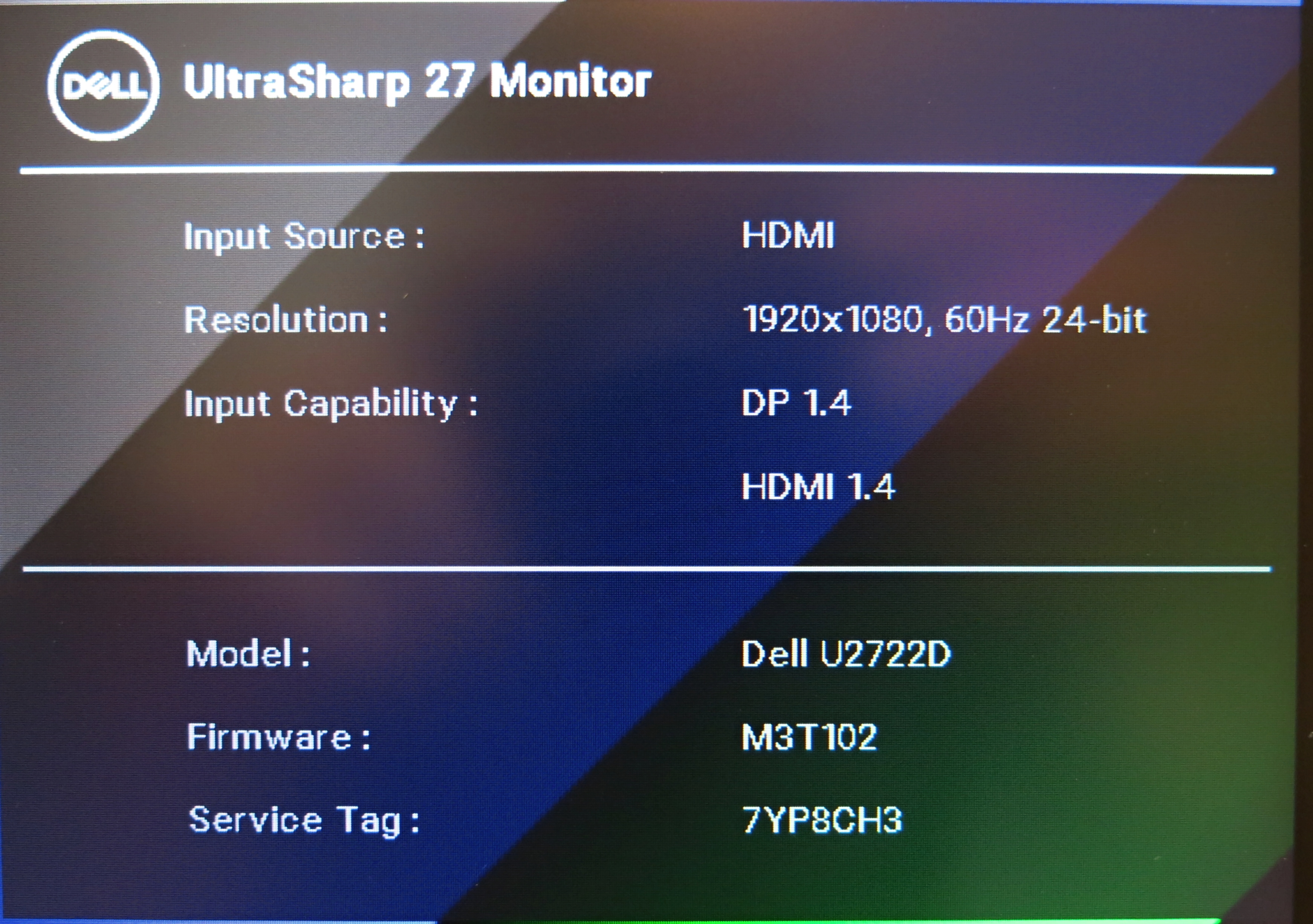
At this point, I can finally say, that the KCU116 really does support a 720p/1080p video output through the HDMI connector, but things are not as easy as they might look like on the first sight from the documentation. First of all, the HDMI output from KCU116 is supported through an external chip from Analog Devices - ADV7511. I originally thought that this would be the easier approach, but after bringing up the interface through this chip, I have to say, that next time, I am doing the complete FPGA HDMI Phy instead. This is because configuration of the ADV7511 itself requires a lot of study, not to mention that despite having a "G" revision, the documentation is sometimes not very clear - especially the 7-bit IIC address shifted for one bit left is a bloody masterpiece! Thank you so much Analog Devices!
I have to add however that not even the Xilinx's documentation for the KCU116 here is among the best that I have seen. I would expect personally, that some information will be provided how to achieve the 1080p YCbCr4:2:2 video mode (Considering the fact, that the engineers must have been though the ADV7511 documentation as well). A simple hint which mode, data alignment and pixel clock (1x? / 2x ?/ DDR?), to use would be really appreciated. But Not a single word on this topic except YCbCr 4:2:2 mode. After realizing that 18 data lines are connected to the ADV7511 (And that only 16 are required for YCbCr 4:2:2), I simply stopped expecting any useful information to be available at all.
The configuration, which I have finally used is 1x Clock (no DDR, just 148.5 MHz), Separate Sync (H_SYNC,V_SYNC,DE), obviously the YCbCr 4:2:2 mode, Input ID = 1, Right-Justified, Style 3 (Revisions G's Table 18). Because I am (Ironically) a big fan of hexa numbers, I really appreciate the Analog Devices's hexa-base documentation style (Write 0x.. to 0x.. - Especially if the register contains additional configuration!). Also the documentation forgot to say "Feel free to play with the order of configuration writes to bring up the ADV7511".
1080p Clocking
When it comes to the clocking part, things could have been done probably also much easier. The KCU116 board has several clocks available for the designer. Here, the 74.25Mhz clock (This is the 720p video clock) would have been probably the Xilinx's recommended clock to use for the HDMI interface. However this clock comes from a fixed-clock oscillator onboard and is connected to the High Density bank! Why is this a problem for 1080p video? Because these banks do not support MMCM/PLL and thus clock synthesis (x2) to 148.5MHz (Which is the required clock frequency for 1080p) is not possible.
Clearly, using an external oscillator with a clock frequency of 148.5 MHz instead would solve all the problems, as this would allow for the usage of a global clock buffer (BUFGCE_DIV) with an optional clock division by 2 for 720p video, but there we are left with useless 74.25 MHz. Fortunately, after some investigation, one realizes that in order to have a 148.5MHz video clock available, the easiest solution is to use the 300MHz reference clock intended for DDR4 Interface and configure the MMCM with (((300 / 25) * 99 / 8 ) = 148.5 MHz, VCO = 1188MHz) . Luckily, this works like a charm!
1080p Video Timing
In order to get the HDMI video working, one needs to also establish the correct video timing for the ADV7511 and 1080p mode. For this purpose, 2 choices are generally available: DoItYourself or use the Xilinx's VTC controller . Because I am no longer a big fan of all all the Xilinx IPs (Especially the AXI QSPI and AXI IIC Controllers) and because writing a Video Timing Controller is an easy task (I do also have some experiences with A818 interface 😇), I have obviously chosen the first option. With a little help from sites such as ProjectF to get the correct blanking times, the VTC is completed in no time!
- Canvas : 2200 x 1125 pixels
- Active Video : 1920 x 1080 pixels
- H_SYNC Duration : 44 (Pixels)
- V_SYNC Duration : 5 (Lines)
- H_BACK_PORCH | H_FRONT_PORCH : [148 | 88] Pixels
- V_BACK_PORCH | V_FRONT_PORCH : [36 | 4] Lines
Here, I have to say, that the ADV7511 supports multipe Sync options, but because generating all these signals is fairly simple along with the DE (Data Enable), I have chosen the "Separate Sync" options with the default polarity settings (Active High). One can also easily verify the correct clock speed: 2200 x 1125 x 60Hz = 148.5MHz.
Color Space Conversion
Having found the correct ADV7511 modes, clock synthesis inside the FPGA and Video Timing for 1080p, the only part that is missing is the YCbCr conversion from (Well, usually) 24-bitRGB. Here, I have to say that it would really made my day to have full RGB support for the ADV7511, but I understand that perhaps due to the lack of available IOs (I didn't check), only the YCbCr mode with 16 data lines is supported. Using just the VPSS for the color conversion will however not solve all the problems. The VPSS can be on one hand configured to include a Color Space Conversion (CSC) from RGB to YCbCr422 (And vise versa), but on the other hand, because it has no initial configuration, one must go over its documentation to find out that the "only" thing that it really does is basically a matrix-vector multiply on a bunch of pixels and that you are free to look for the coefficients somewhere else. Here,I can jsut recommend to lookup the ITU-709 documentation, which I have used and convert the coefficients to the appropriate format as required by the VPSS.
Also - one needs to take extra care about the RGB mapping as Xilinx's tools use [R B G] data format rather than RGB. For more information, feel free to look for UG934. Also be aware that YCbCr 422 has a reduced chroma in the horizontal direction - This eventually needs to be implemented also for DIY projects, but doesn't really represent a visible loss of image quality (At least based on my own observation)😇
After all the hassle with the initial platform bring up, the only thing thats missing is the Test Pattern Generator (TPG) and/or video output to use. For the purpose of this post, I have used my own TPG 👀 I just personally prefer a "Moving" pattern rather than a static one, but building a custom TPG is very straightforward as well (I was only lazy to capture the entire screen with a camera, so I rather simulated the below GIF animation of the TPG). As always, feel free to contact me for more details! 🐾