
Video Mixer IP
Overview
The Video Blender/Mixer IP is a highly-configurable full-featured multi-channel video mixer. It supports generic amount AXI-compliant video stream channels, which can be arbitrary repositioned, cropped, chroma-keyed and/or blended together on a common canvas. All of the standard parameters including the channel alpha, position, visibility range, chroma key parameters and background color are run-time configurable.Canvas size is bound by generic definitions. The input video streams are automatically synchronized to have the required portions of data available whenever necessary to draw them on the canvas. To balance between the performance of the IP (Throughput) and resources required, one can choose the necessary amount of parallel pipelines, which are used to draw the defined canvas in parallel.

Demo-Topology
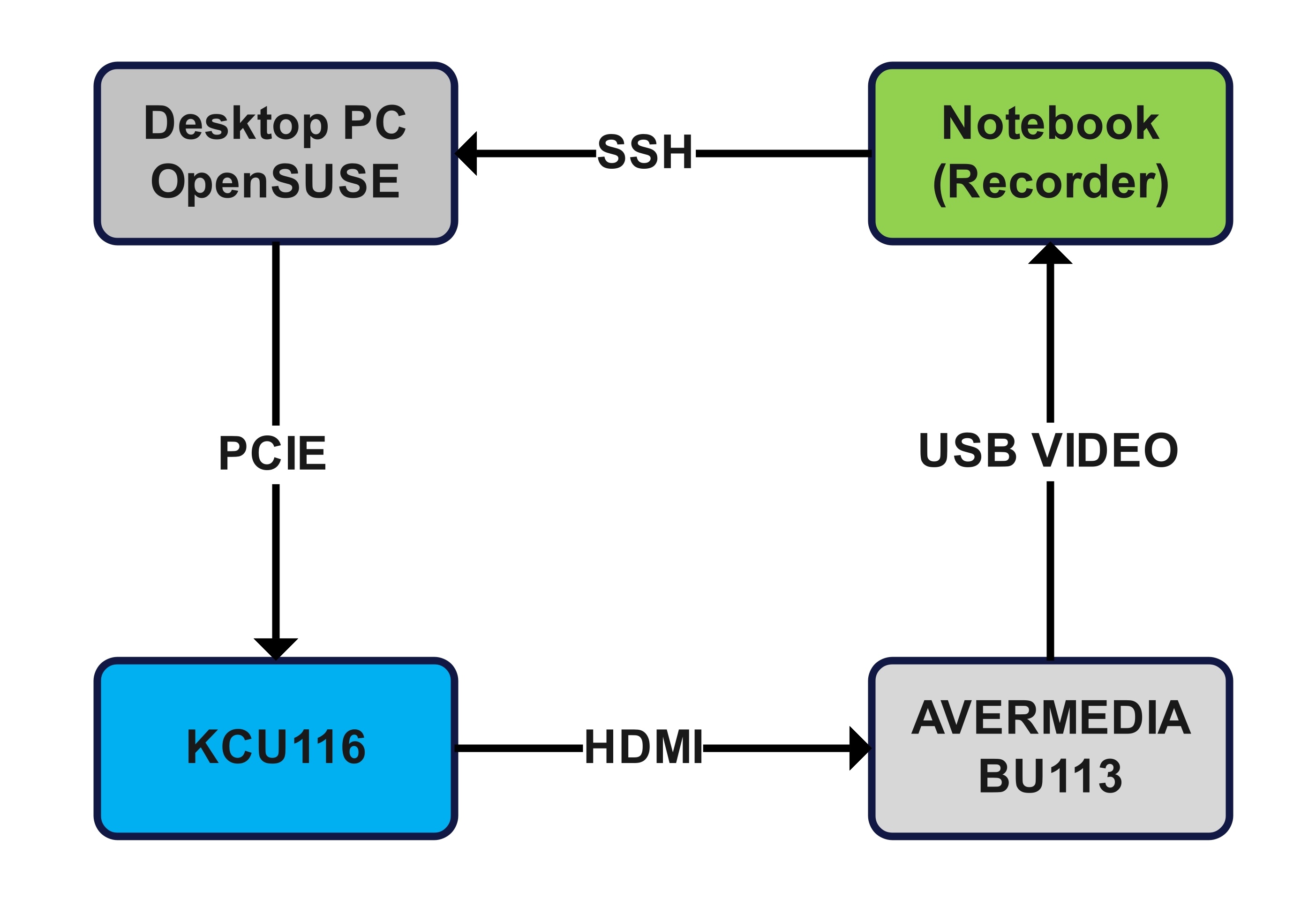
The demonstration setup consists of the following main items:
- Arbitrary PC running the (Preferably) OBS application in order to capture and store the Video.
It is recommended that the recording platform has a support for HW video encoding (IE GPU). - Capture Device with a support for HDMI input at a FullHD resolution (1920x1080@60Hz).
For this demonstration, the AverMedia BU113 is used. - Arbitrary Desktop PC with PCIe x8/x16 slot preferably with Gen 3.0+ and optional PCIe riser cables.
Can also be used as a record PC. This device has the necessary Linux Kernel PCIe drivers installed.
A user-space control application (with GUI) is used to control the capabilities of of the FPGA through the kernel drivers.
Any standard Linux distribution can be used. OpenSUSE has just been chosen due to my own preferences. - KCU116 Board with further configuration listed in its section.
Demo - FPGA Configuration
The KCU116 is configured to produce a Full-HD video resolution (1920x1080@60Hz) over the ADV7511 device located on the board. The FPGA includes the AMD's XDMA IP (PG194) in AXI to bridge mode and AMD's DDR4 Memory IP (PG150). All other remaining IPs including the Video Buffer IP and the Video Mixer IP are proprietary as well as the entire AXI infrastructure.
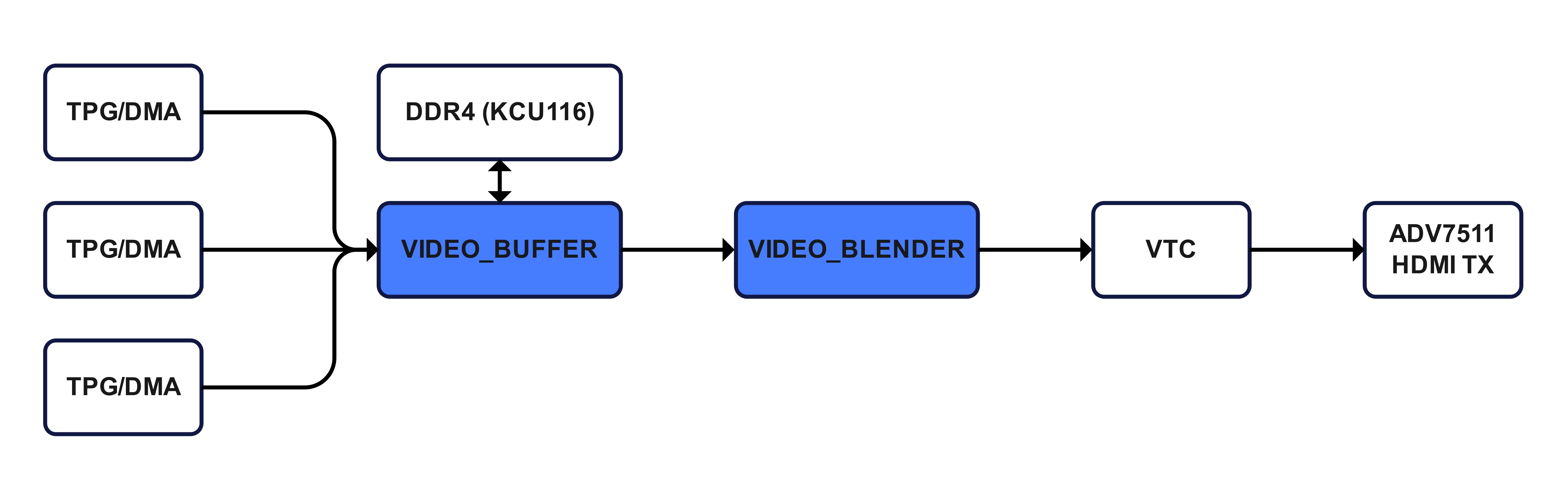
The Video Buffer and Video Blender IPs are configured to support 3 independent Video Channels (Through Generics). All of the Test Pattern Generators (TPG) are running on AXI Infrastructure clock (250MHz). The core of the Video Buffer and Video Blender run on the DDR4-2400 memory clock (300MHz) and the remaining Video TX pipeline including the VTC (Video Timing Controller) run on the 148.5MHz clock to satisfy the necessary video timing. The TPGs are configured to FHD resolution and can be switched to DMA-Video over PCIe. As such, the TPG Video sources generate a memory traffic equivalent to 120Hz FHD. In order to minimize the video latency, the video buffer arbiter maintains 3 buffers within the DDR4 memory.
Demo - Software Control Application
The Software control application is a generic C++ application with a GUI, that interacts with the PCIe Linux Kernel drivers over a simple IOCTL Interface. All of the 3 video channels presented on a per-tab basis can be adjusted with a sliders / combo boxes and/or check boxes. Slider values for alpha range from 0.0f to 1.0f (But are converted to Q9.8u). Position and visibility of the channels ranges according to the canvas resolution (FHD 1920 x 1080). Chroma Keying parameters are based on the color format definitions. For RGB888 used in the demo, each of those values is within the 0-255 range.
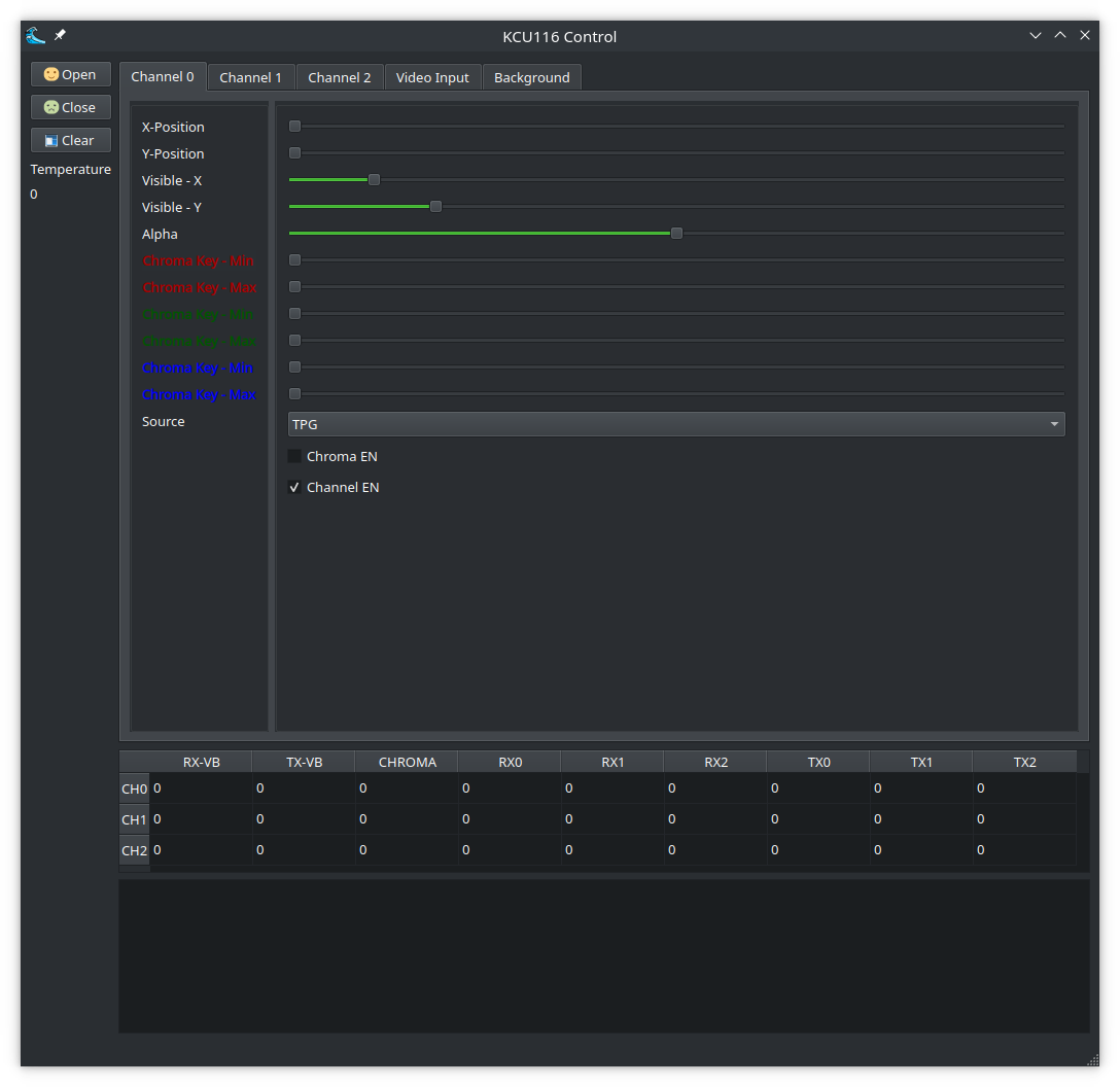
Table in the middle represents (some of) the statistics from the FPGA across all the channels:
- RX-VB: Total amount of Received Frames (IE Written to DDR4)
- TX-VB: Total amount of Transmitted Frames (IE Read from DDR4)
- CHROMA: Amount of pixels per last drawn frame, that has been affected by chroma-keying parameters.
- RX0 - RX2: Same as 1, on a per-video-buffer basis
- TX0 - TX2: Same as 2, on a per-video-buffer basis
The section in the bottom of the application is used for console output.
Background Tabulator contains 3 boxes to apply RGB values for the Canvas background.
Video Input allows to send an arbitrary image over PCIe for blending via DMA in RGBA format.
IE: 1920x1080 Image requires a DMA transfer of ~8MB.
NOTE: The application might be run over X11-Forward within the demo.
Features
- Reposition all video channels as necessary around the canvas
- Crop all video channels according to your needs
*The build-in video cropper is not a full-featured cropper - Setup alpha blending constants across all video channels
- Apply chroma keying among the selected channels
- Setup custom video background color
- Dynamically enable/disable selected channels
- AXI4-Lite Status & control Interface
- Linux kernel drivers provided in C.
- Verified both in simulation and on Hardware
Full RTL-code base written in modern VHDL2008 along with documentation and TBs. Architecture / vendor independent.
FAQ
- Are only 3 video channels supported?
No, you can configure the IP with an arbitrary amount of video channels throught the generics. For practical reasons (Performance and resources), consider limiting amount of channels to ~8. The demo utilizes only 3 video channels to show that also non power-of-2 configurations are supported and also to speedup the development and compilation. - Why the TPG in the demo runs at a framerate of ~120Hz?
The TPG's internal clockrate is 250 MHz. Given a FullHD resolution, the framerate is given by (250e6 / (1920x1080)). - What is the maximum output canvas resolution?
There is no maximum canvas resolution. However note that the IP might draw at maximum 1 pixel per clock cycle. This imposes limits to the maximum refresh rate/resolution based on what the underlying FPGA device is capable of (In terms of clock Speed). To balance between the resources and performance, the IP can be configured to include arbitrary amount of parallel drawing pipelines. - Can the IP be used on non Xilinx's (AMD) FPGAs?
Currently, the Video Blender IP is vendor-independent, however the Video Buffer IP utilizes some of the AMD's interfaces ( Namely the DDR4 User Interface definitions). If you wish to target non-AMD device, please contact me for rework estimates and requirements on the targetted DDR interface. - What is the maximum supported clock speed?
This largely depends on the used FPGA, its speed grade, design complexity and amount of available remaining resources on the chip. The IP is generally optimized for performance, but if you encounter some configuration, that dosnt meet timing, please contact me and I will try my best to fix that.
NOTE: The IP’s resource estimates and ~FMAX timing performance were evaluated with Vivado 2024.2 tool on OpenSuse Linux 15.6 targetting xcku5p-ffvb676-2-e device (KCU116 – Kintex Ultrascale+) or xcu50-fsvh2104-2-e (Alveo U50 – Virtex Ultrascale+). All evaluation was done with the default tool configuration for Synthesis / Optimization / Place & Route. Due to the excessive amount of possible IP configuration, only a few selected configurations are shown. Non-power of two video channels are supported also. Amount of parallel pipelines helps in achieving the necessary IP performance. For more details, please contact me directly.
Resources & Timing - 1CH
| Pipes | LUTs[k] | FFs[K] | BRAM36 | DSP48 | FMAX [MHz] |
| 1 | 1.5 | 2.1 | 0 | 3 | 500 |
| 2 | 2.1 | 2.7 | 0 | 6 | 500 |
| 3 | 2.9 | 3.3 | 0 | 9 | 500 |
| 4 | 3.6 | 3.9 | 0 | 12 | 500 |
| 5 | 4.3 | 4.6 | 0 | 15 | 500 |
| 6 | 4.9 | 5.2 | 0 | 18 | 500 |
| 7 | 5.7 | 5.8 | 0 | 21 | 500 |
| 8 | 6.4 | 6.4 | 0 | 24 | 500 |
| 9 | 7.0 | 7.0 | 0 | 27 | 500 |
Resources & Timing - 2CH
| Pipes | LUTs[k] | FFs[K] | BRAM36 | DSP48 | FMAX [MHz] |
| 1 | 2.1 | 3.1 | 0 | 3 | 500 |
| 2 | 2.9 | 4.0 | 0 | 6 | 500 |
| 3 | 3.9 | 4.8 | 0 | 9 | 500 |
| 4 | 4.7 | 5.7 | 0 | 12 | 500 |
| 5 | 5.6 | 6.5 | 0 | 15 | 500 |
| 6 | 6.4 | 7.5 | 0 | 18 | 500 |
| 7 | 7.3 | 8.3 | 0 | 21 | 500 |
| 8 | 8.2 | 9.1 | 0 | 24 | 500 |
| 9 | 9.0 | 10.0 | 0 | 27 | 500 |
Resources & Timing - 4CH
| Pipes | LUTs[k] | FFs[K] | BRAM36 | DSP48 | FMAX [MHz] |
| 1 | 3.7 | 5.1 | 0 | 3 | 500 |
| 2 | 5.2 | 6.3 | 0 | 6 | 500 |
| 3 | 6.7 | 7.6 | 0 | 9 | 500 |
| 4 | 8.2 | 8.8 | 0 | 12 | 500 |
| 5 | 9.6 | 10.1 | 0 | 15 | 500 |
| 6 | 11.1 | 11.3 | 0 | 18 | 500 |
| 7 | 12.6 | 12.6 | 0 | 21 | 500 |
| 8 | 14.1 | 13.8 | 0 | 24 | 500 |
| 9 | 15.6 | 15 | 0 | 27 | 500 |
Resources & Timing - 8CH
| Pipes | LUTs[k] | FFs[K] | BRAM36 | DSP48 | FMAX [MHz] |
| 1 | 5.7 | 9.1 | 0 | 3 | 450 |
| 2 | 7.4 | 11.1 | 0 | 6 | 450 |
| 3 | 9.1 | 13.1 | 0 | 9 | 450 |
| 4 | 10.8 | 15.0 | 0 | 12 | 450 |
| 5 | 12.3 | 17.0 | 0 | 15 | 450 |
| 6 | 14.0 | 19.0 | 0 | 18 | 450 |
| 7 | 15.6 | 21.0 | 0 | 21 | 450 |
| 8 | 17.1 | 23.0 | 0 | 24 | 450 |
| 9 | 19 | 25.0 | 0 | 27 | 450 |

Please make sure to watch the real-time demo application and contact me directly for detailed documentation and delivery options! The IP functionality can also be evaluated real-time over an online meeting (MS Teams / Google Meet / Zoom) or directly on site upon previous agreement. Additional customizations and/or adjustments are also negotiable. The IP comes with a reference linux kernel drivers.
Thank you